Product Description
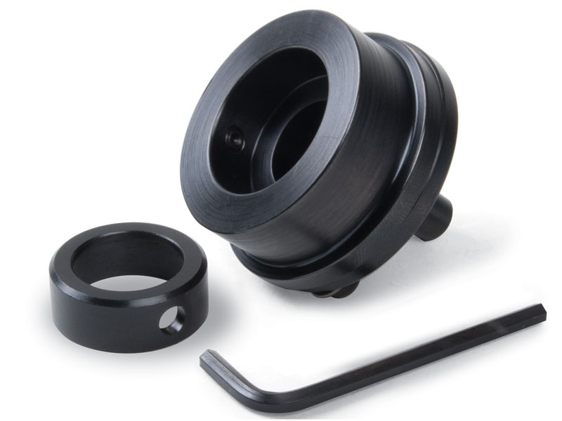
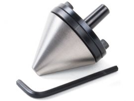
The 1″ die holder utilizes a split plate design to achieve centering accuracy. A 1″ button die is held in the face plate, and shafts held in a chuck or collet in the lathe headstock spindle can be threaded. The tailstock is not tightened to the bed, so the die is free to feed itself onto the part as the part is rotated by hand with the spindle, preferably with the large handwheel from the thread-cutting attachment or the #2049 Spindle Handwheel. Included is a 13/16″ bushing that allows smaller dies of that size to be held as well.
Much like the adjustable live center, holding a die in perfect alignment in the tailstock without some method of adjusting it can be difficult or impossible. To achieve perfect centering, the die is mounted in a front plate. The rear plate has the #0 Morse taper that goes in the tailstock spindle. Slightly oversize holes in the rear plate allow the two plates to be adjusted in relationship to each other so that the die can be brought into perfect alignment with the headstock. This is an economical way to have the accuracy of an adjustable tailstock for those who need it while keeping costs down for those who don’t.
The accuracy that is attainable by adjustable tailstock tools is governed by the amount of skilled effort you put forth. Only someone new to the machine trade would talk about “perfect” alignment. In the machine business, you talk tolerances even if you can’t measure an error because now the error has to be assumed from the tolerances of your method of checking.
These holders are simple to use. The holders are divided into two parts with flanges. These flanges are bolted together with two screws. The clearance holes for these screws allow the front to be adjusted in relation to the rear. The rear section has a witness mark (groove). This mark should always be located at the top so the holder is located the same way in the tailstock each time.
